20 KiB
OpenIPC Wiki
OpenIPC firmware installation, step by step.
Step 1. Determine the CPU chip
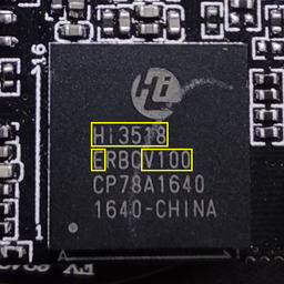
Hisilicon Hi3518EV100 SoC marking. Relevant symbols highlighted with yellow.
Step 2. Download the firmware.
Go to https://github.com/OpenIPC/firmware and find your SoC in the table of supported hardware. Make sure there is a downloadable binary file for that SoC. If you are lucky and there is a pre-compiled firmware file for your processor -- download it onto your PC.
Step 3. Install and set up a TFTP server.
TFTP stands for Trivial File Transfer Protocol. As the name implies, it is a very simple protocol intended for transferring files over a local computer network. TFTP does not support authentication. Its code is so tiny and simple that TFTP-clients are widely used in thin-clients and embedded systems for retrieving bootable images from a designated boot server on the local network.
If you have Linux...
...then it's easy. Pre-compiled and ready-to-use binary package for your distro most likely already exists in distro's repo, and you only need to install it and set it up.
sudo apt install tftpd-hpa
sudo sed -i '/^TFTP_OPTIONS/s/"$/ --create"/' /etc/default/tftpd-hpa
sudo systemctl restart tftpd-hpa.service
Now you've got your own TFTP server serving files from /srv/tftp directory.
Extract files from the bundle you downloaded in step two into that directly.
sudo tar -C /srv/tftp/ -xvf openipc.*.tgz
Step 4. Connect to UART port of your camera.
In order to make a connection to UART port you will need a serial port adapter for your PC.
Before you connect that adapter to you camera, make sure that it's working voltage is set to 3.3 volt! Sometimes, you only need to flip a jumper to achieve that. But in some cases you might need to solder a wire, a zero Ohm resistor, or make a connection between two contacts with a blob of solder. Some adapters support only 5 volt. In that case, you will need an additional logic level converter connected between the adapter and UART port on your camera.
One of the contact pads you will need to connect you adapter to is GND (ground).
It is easy to discover using a multimeter in continuity mode. Put one of the
leads onto a well-known exposed ground pads. Usually, these are large open
copper contact areas around mounting screw holes, USB port housing, SD card slot
metallic walls. Use another lead to slightly touch control pads until you see or
hear a notification from your multimeter that the circuit is closed. That means,
you found the ground. Now, you need to find two more: RX and TX, both used
for receiving and transmitting data, respectively. Start with TX. It transmits
series of characters and quite easy to spot.
Be aware that you are looking for a contact with 3.3v potential between it and the ground. Test possible connection points with a multimeter and mark those showing 3.3 volt. This way you won't have to test everything, and you save yourself from hitting say a 12 volt connector intended for infrared LED array or whatnot.
Connect GND pin on your camera to GND pad of the adapter, connect USB
connector of the adapter to a USB port on your PC, start a terminal emulator
application and connect to your adapter. Use connection speed of 115200 bps,
no flow control, no parity bit.
Then, connect RX pin on the adapter to a possible TX contact of UART port
on your camera. Power the camera with its standard power adapter. If you had a
lucky guess then you'll start seeing booting log in your terminal window. In
some cases, if you see garbled text on you screen instead of booting kernel,
you might need to change the connection speed to 57600 bps and try again.
If your screen remains blank, try another UART contact, and then another, until you hit the proper one.
After you found the TX pad, connect it to RX pin on your adapter. Yes, it is
a cross-connection. Whatever transmits goes into a receiver and vice-versa. Now,
put a heavy object -- a railroad nut, an antique tin solder, a shot of vodka
(full) -- on any letter key of your computer keyboard and start connect
remaining TX pin of your adapter to different pads on the camera until you see
it backfeeding to the terminal. As it happens, you have successfully completed
a UART connection to you camera. Now you may drink the vodka.
NB! Usually, there is a fourth contact on a UART connector marked VCC. It is
used for powering camera during initial programming by manufacturer. We strongly
advise not to power your camera though that pin, but use the OEM power connector
for this purpose.
Step 5. Get access to the bootloader.
Reboot the camera and try to interrupt its boot sequence in order to access
bootloader console by pressing a key combination on your computer keyboard,
between the time the bootloader starts and before Linux kernel kicks in.
Key combinations differ from vendor to vendor but, in most cases, it is
Ctrl-C, less commonly -- Enter, Esc or just any key. Carefully read text
appearing on screen while booting, you might see a hint there. Some cameras
require more exotic combinations not revealed in booting logs. You may try to
look them up on the internet, or ask on our Telegram channel.
Chances are, we have already dealt with such a camera and know the combo.
If you succeeded and got a command prompt then congrats, you've got access to your camera's bootloader.
From this point on, we strongly advise you to keep a record of everything you do. Enable session logging in your terminal. Even better, create a text file on your computer and write down all commands you run and how system responses to them.
Step 6. Save the original firmware.
After you get access to the bootloader console, run help to get a list of
available commands. Check if you have tftp among them. If you do, then saving
the original firmware should be a breeze. You only need to set up access to your
TFTP server from step 3.
NB! If your bootloader does not have tftp, you can still make a copy of the
original firmware. Read here for more.
Check the system environment using printenv command. Look for ipaddr,
netmask, gatewayip and serverip parameters. The first three set IP address,
netmask of your camera, and the IP address of the network gateway for accessing
local network. The fourth parameter is an IP address of your TFTP server. Assign
the values by setenv command (use IP addresses and netmask corresponding to
your local network), then save the new values into environment with saveenv
command.
setenv ipaddr 192.168.1.253
setenv netmask 255.255.255.0
setenv gatewayip 192.168.1.1
setenv serverip 192.168.1.254
saveenv
Most IP cameras nowadays are equipped with 8 or 16 MB NOR or NAND flash memory. You can check the type and size of the chip installed on of your camera in the bootloader log output. You'll see something like this:
U-Boot 2010.06-svn (Oct 21 2016 - 11:21:29)

Check Flash Memory Controller v100 ... Found
SPI Nor(cs 0) ID: 0xс2 0x20 0x18
spi_general_qe_enable(294): Error: Disable Quad failed! reg: 0x2
Block:64KB Chip:16MB Name:"MX25L128XX"
SPI Nor total size: 16MB
To dump the original firmware, you need to save the contents of camera's flash memory to a file. For that, you must first load the contents into RAM. Here's how you do that. Initialize the Flash memory. Clean a region of RAM of 0x1000000 bytes long starting from address 0x82000000*. Read contents of the Flash from address 0x0 0x1000000 bytes long and place it into the prepared region or RAM. Now, you only have to export it to a file on the TFTP server.
sf probe 0
mw.b 0x82000000 ff 0x1000000
sf read 0x82000000 0x0 0x1000000
tftp 0x82000000 firmware-full.bin 0x1000000
NB! Please note, that the starting address and length will be different for different cameras with different Flash memory chips. Consult data sheets or seek help on our Telegram channel.
Step 7. Install OpenIPC firmware.
Part one.
No two camera models are alike. Different camera models consist of different sets of components. The most important of them, the central processor and the image sensor, directly affect the image quality and the range of functions inherent in a particular camera. Unlike desktop computer CPU, camera's processor handles so many functions that it got a specific name -- System-on-Chip or SoC, for short.
But even seemingly less significant components can set limitations on the camera and its firmware capabilities. For example, different cameras may have different flash memory chips installed. Some cameras may have 8MB of flash memory, while others may have 16MB or more. More flash memory can fit more software code and allow the camera to run additional services that are not available on cameras with less flash memory. So we decided to build two versions of our firmware: the basic version (Lite) for cameras with 8 MB of flash memory and the advanced version (Ultimate) with additional features for cameras with 16 MB flash memory.
As said before, firmware installation routine differs for different cameras. There are different memory addresses and different environment parameters, so before proceeding, determine what kind of SoC is in your camera, what sensor, what flash memory chip and what amount of memory is has.
Below we describe the procedure for installing the OpenIPC Lite firmware on a camera with 8 MB of flash memory, as an example. Even if your camera has larger flash memory, do not skip this text. Read it carefully to understand the principle and the sequence of operations. We will provide specific commands for different cameras in the second part of this section.
Preparation.
So, we have a guinea pig, a camera with hi3518ev100 SoC, equipped with a OV9712 sensor and 64 MB of RAM.
Connect to the camera via the UART port and access the bootloader console. Set the component parameters to the appropriate environment variables:
setenv soc hi3518ev100
setenv sensor ov9712
setenv totalmem 64M
Set environment variables for loading the Linux kernel and the root file system of the new firmware:
setenv osmem 32M
setenv bootargs 'mem=${osmem:-32M} console=ttyAMA0,115200 panic=20 root=/dev/mtdblock3 rootfstype=squashfs init=/init mtdparts=hi_sfc:256k(boot),64k(env),2048k(kernel),5120k(rootfs),-(rootfs_data)'
setenv bootcmd 'setenv setargs setenv bootargs ${bootargs}; run setargs; sf probe 0; sf read 0x82000000 0x50000 0x200000; bootm 0x82000000'
Set environment variables for the camera to access local network, where
ethaddr is the original camera MAC address, ipaddr is camera's IP address
on the network, gatewayip is the IP address of a router to access the network,
netmask is the subnet mask, and serverip is am IP address of the TFTP server
from step 3.
setenv ethaddr 00:12:16:00:00:00
setenv ipaddr 192.168.1.10
setenv netmask 255.255.255.0
setenv gatewayip 192.168.1.1
setenv serverip 192.168.1.254
Save updated values to flash memory.
saveenv
Installation.
First, clear the memory region at address 0x82000000, 0x1000000 bytes long, by writing 0xff to it. Then retrieve kernel file for the camera from the TFTP server and place it into memory starting with address 0x82000000.
The $soc variable in the name of the requested file is substituted with its
value from the environment variables created earlier. In this example, the file
named uImage.hi3518ev100 will be requested from the server.
mw.b 0x82000000 ff 1000000
tftp 0x82000000 uImage.${soc}
NB! Pay attention to the messages on the terminal screen! If any of the commands throws an error, find out what went wrong. Maybe you made a typo? In any case, do not continue the procedure until all previous commands succeed. Otherwise, you might end up with a bricked camera!
So, you've made sure that the file is downloaded and placed in the camera's RAM. Now you need to write it down to the flash memory. To do that, you need to get access to the flash memory, then clean erase the region from address 0x50000 that is 0x200000 bytes long, and copy the contents of camera's RAM from address 0x82000000 and the size of the kernel file to the flash memory starting at address 0x50000.
sf probe 0
sf erase 0x50000 0x200000
sf write 0x82000000 0x50000 ${filesize}
Next, you need to repeat the process for the root file system, saving it to the next region starting from address 0x250000 of 0x500000 bytes long.
NB! 0x500000 bytes is a hexadecimal equivalent of 5242880 bytes in decimal
system, and equals 5120 kilobytes, exactly what we have prepared for rootfs
in bootargs parameter.
It is easy to memorize the sequence if you give it a little thought: clean RAM, download file there, unlock flash chip, wipe the target region in flash memory, write file from memory into there.
mw.b 0x82000000 ff 1000000
tftp 0x82000000 rootfs.squashfs.${soc}
sf probe 0
sf erase 0x250000 0x500000
sf write 0x82000000 0x250000 ${filesize}
After both partitions have been successfully written to the flash memory and all necessary changes have been made to the bootloader to prepare it for starting the new firmware, it is time to reboot the camera. To do that, type this command in the console:
reset
Part two.
If you have read the first part of this section (if not - go read it), then you already know what manipulations and why you need to do to install the OpenIPC firmware. And all you need are the commands suitable for your particular camera.
Below are samples of such commands for cameras equipped with Goke, HiSilicon, SigmaStar/MStar, XM SoCs.
Goke
SoC: gk7202v300, gk7205v200, gk7205v300
setenv soc <processor>   # gk7202v300, gk7205v200, or gk7205v300.
setenv sensor <sensor>   #
setenv totalmem <memory> # 64M for gk7202v300, gk7205v200, 128M for gk7205v300.

setenv osmem 32M
setenv bootargs 'mem=${osmem:-32M} console=ttyAMA0,115200 panic=20 root=/dev/mtdblock3 rootfstype=squashfs init=/init mtdparts=sfc:256k(boot),64k(env),2048k(kernel),5120k(rootfs),-(rootfs_data)'
setenv bootcmd 'setenv setargs setenv bootargs ${bootargs}; run setargs; sf probe 0; sf read 0x42000000 0x50000 0x200000; bootm 0x42000000'

setenv ethaddr 00:00:00:00:00:00
setenv ipaddr 192.168.1.10
setenv netmask 255.255.255.0
setenv gatewayip 192.168.1.1
setenv serverip 192.168.1.254

saveenv

mw.b 0x42000000 ff 1000000
tftp 0x42000000 uImage.${soc}
sf probe 0
sf erase 0x50000 0x200000
sf write 0x42000000 0x50000 ${filesize}

mw.b 0x42000000 ff 1000000
tftp 0x42000000 rootfs.squashfs.${soc}
sf probe 0
sf erase 0x250000 0x500000
sf write 0x42000000 0x250000 ${filesize}

reset
HiSilicon
SoC: hi3516ev200, hi3516ev300, hi3518ev300.
setenv soc <processor>   # hi3516ev200, hi3516ev300, or hi3518ev300.
setenv sensor <sensor>   #
setenv totalmem <memory> # 64M for hi3516ev200, hi3518ev300, 128M for hi3516ev300.

setenv osmem 32M
setenv bootargs 'mem=${osmem:-32M} console=ttyAMA0,115200 panic=20 root=/dev/mtdblock3 rootfstype=squashfs init=/init mtdparts=hi_sfc:256k(boot),64k(env),2048k(kernel),5120k(rootfs),-(rootfs_data)'
setenv bootcmd 'setenv setargs setenv bootargs ${bootargs}; run setargs; sf probe 0; sf read 0x42000000 0x50000 0x200000; bootm 0x42000000'

setenv ethaddr 00:00:00:00:00:00
setenv ipaddr 192.168.1.10
setenv netmask 255.255.255.0
setenv gatewayip 192.168.1.1
setenv serverip 192.168.1.254

saveenv

mw.b 0x42000000 ff 1000000
tftp 0x42000000 uImage.${soc}
sf probe 0
sf erase 0x50000 0x200000
sf write 0x42000000 0x50000 ${filesize}

mw.b 0x42000000 ff 1000000
tftp 0x42000000 rootfs.squashfs.${soc}
sf probe 0
sf erase 0x250000 0x500000
sf write 0x42000000 0x250000 ${filesize}

reset
SigmaStar/MStar
SoC: ssc325, ssc335, ssc337.
setenv soc <processor>   # ssc325, ssc335, or ssc337.
setenv sensor <sensor>   # gc2053, imx307, or sc3335.
setenv totalmem 64M

setenv osmem 32M
setenv bootargs 'mem=${osmem:-32M} console=ttyS0,115200 panic=20 root=/dev/mtdblock3 rootfstype=squashfs init=/init LX_MEM=0x3fe0000 mma_heap=mma_heap_name0,miu=0,sz=0x1C00000 mma_memblock_remove=1 mtdparts=NOR_FLASH:256k(boot),64k(tech),2048k(kernel),5120k(rootfs),-(rootfs_data)'
setenv bootcmd 'setenv setargs setenv bootargs ${bootargs}; run setargs; sf probe 0; sf read 0x21000000 0x50000 0x200000; bootm 0x21000000'

setenv ethaddr 00:00:00:00:00:00
setenv ipaddr 192.168.1.10
setenv netmask 255.255.255.0
setenv gatewayip 192.168.1.1
setenv serverip 192.168.1.254

saveenv

mw.b 0x21000000 ff 1000000
tftpboot 0x21000000 uImage.${soc}
sf probe 0
sf erase 0x50000 0x200000
sf write 0x21000000 0x50000 ${filesize}

mw.b 0x21000000 ff 1000000
tftpboot 0x21000000 rootfs.squashfs.${soc}
sf probe 0
sf erase 0x250000 0x500000
sf write 0x21000000 0x250000 ${filesize}

reset
XM
SoC: xm510, xm530, xm550.
setenv soc <processor>   # xm510 for xm510, xm530 for both xm530 and xm550.
setenv sensor <sensor>   #
setenv totalmem <memory> # 32M for xm510, 64M for xm530, 128M for xm550.

setenv osmem <osmemory>  # 18M for xm510, 35M for xm530, 64M for xm550.
setenv bootargs 'mem=35M console=ttyAMA0,115200 panic=20 root=/dev/mtdblock3 rootfstype=squashfs init=/init mtdparts=xm_sfc:256k(boot),64k(env),2048k(kernel),5120k(rootfs),-(rootfs_data)'
setenv bootcmd 'sf probe 0; sf read 0x80007fc0 0x50000 0x200000; bootm 0x80007fc0'

setenv ethaddr 00:00:00:00:00:00
setenv ipaddr 192.168.1.10
setenv netmask 255.255.255.0
setenv gatewayip 192.168.1.1
setenv serverip 192.168.1.254

saveenv

mw.b 0x80007fc0 ff 1000000
tftp 0x80007fc0 uImage.${soc}
sf probe 0
sf erase 0x50000 0x200000
sf write 0x80007fc0 0x50000 ${filesize}

mw.b 0x80007fc0 ff 1000000
tftp 0x80007fc0 rootfs.squashfs.${soc}
sf probe 0
sf erase 0x250000 0x500000
sf write 0x80007fc0 0x250000 ${filesize}

reset
Step 8. First boot.
If all previous steps are done correctly, your camera should start with the new firmware. Welcome to OpenIPC!
After the first boot with the new firmware you need to clean the overlay partition. Run this in your terminal window:
firstboot
Step aside.
To facilitate subsequent firmware upgrades directly from the bootloader console, create two macros with sequences of commands needed to boot from the TFTP server and write kernel and root file system for your camera model into flash memory.
We will use uk and ur for macro names, which can be decoded as update kernel
and update rootfs. Easy to remember.
As you remember, in the example above we used the following commands to install the kernel:
mw.b 0x42000000 ff 1000000
tftp 0x42000000 uImage.${soc}
sf probe 0
sf erase 0x50000 0x200000
sf write 0x42000000 0x50000 ${filesize}
To create the uk macro, join all the above commands into one line, alternating
them with semicolons. For added protection against writing invalid data to flash
memory in case file downloading from TFTP server fails, replace semicolon before
sf probe 0 with logical AND operator (&&). It will make macro to abort if
file fails to download.
fw_setenv uk 'mw.b 0x42000000 ff 1000000; tftp 0x42000000 uImage.${soc} && sf probe 0; sf erase 0x50000 0x200000; sf write 0x42000000 0x50000 ${filesize}'
Do the same with the root file system commands:
mw.b 0x82000000 ff 1000000
tftp 0x82000000 rootfs.squashfs.${soc}
sf probe 0
sf erase 0x250000 0x500000
sf write 0x82000000 0x250000 ${filesize}
saving result as ur macro:
fw_setenv ur 'mw.b 0x42000000 ff 1000000; tftp 0x42000000 rootfs.squashfs.${soc} && sf probe 0; sf erase 0x250000 0x500000; sf write 0x42000000 0x250000 ${filesize}'
Naturally, to create your own macro, you should use the commands suitable for your specific camera, not mindlessly copying the above lines, but using them as an example and understanding the actions to be taken.
NB! Although these commands create a macro to run in the bootloader console,
they must be executed inside Linux environment. This way we avoid the
restrictions on the number of arguments in the setenv command existing in
some older versions of the bootloader.
You will now be able to flash both kernel and root file system followed by rebooting the camera directly from the bootloader console. It's as easy as that!
run uk; run ur; reset